This is actually a project I did quite a while ago (the git repository goes back to September 2014), when the WS2812 LEDs became really popular and ubiquitous. Naturally, I had to get a 5 metre strip of them as well, to play around with them. And what would you do with them? A clock of course!
At the time, I was also very much against just throwing an Arduino at it and being done with it, because I thought even that would be overkill. (Though it actually started as a real-time clock module for an Arduino Nano.) I had made an alarm clock before and knew, that the Arduino wasn’t doing anything most of the time, since I’d be using at dedicated real-time clock chip. The Arduino would most of the time just be idling and waiting for the interrupt, generated by the clock chip.
And I also wanted to learn to design and manufacture my own PCBs. dermeb already did that several years ago, when he designed, etched and build BlinkenLED displays. So we still had the basic chemicals sitting in the basement waiting to be used again.
Concept
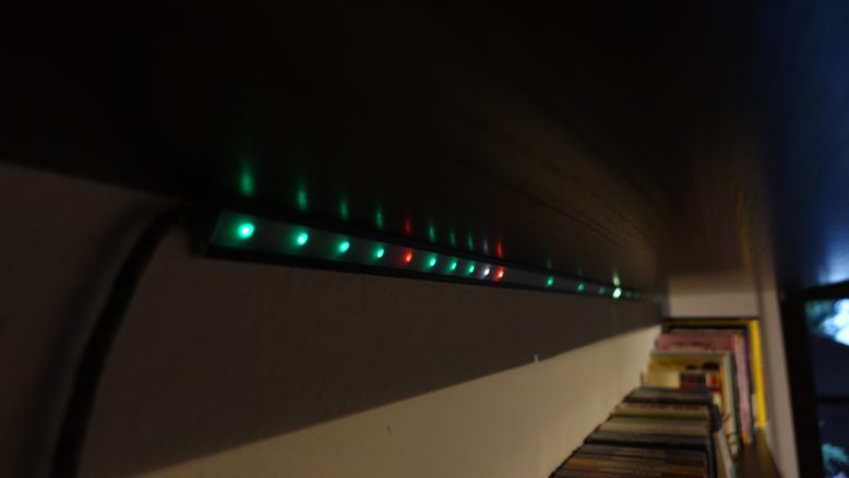
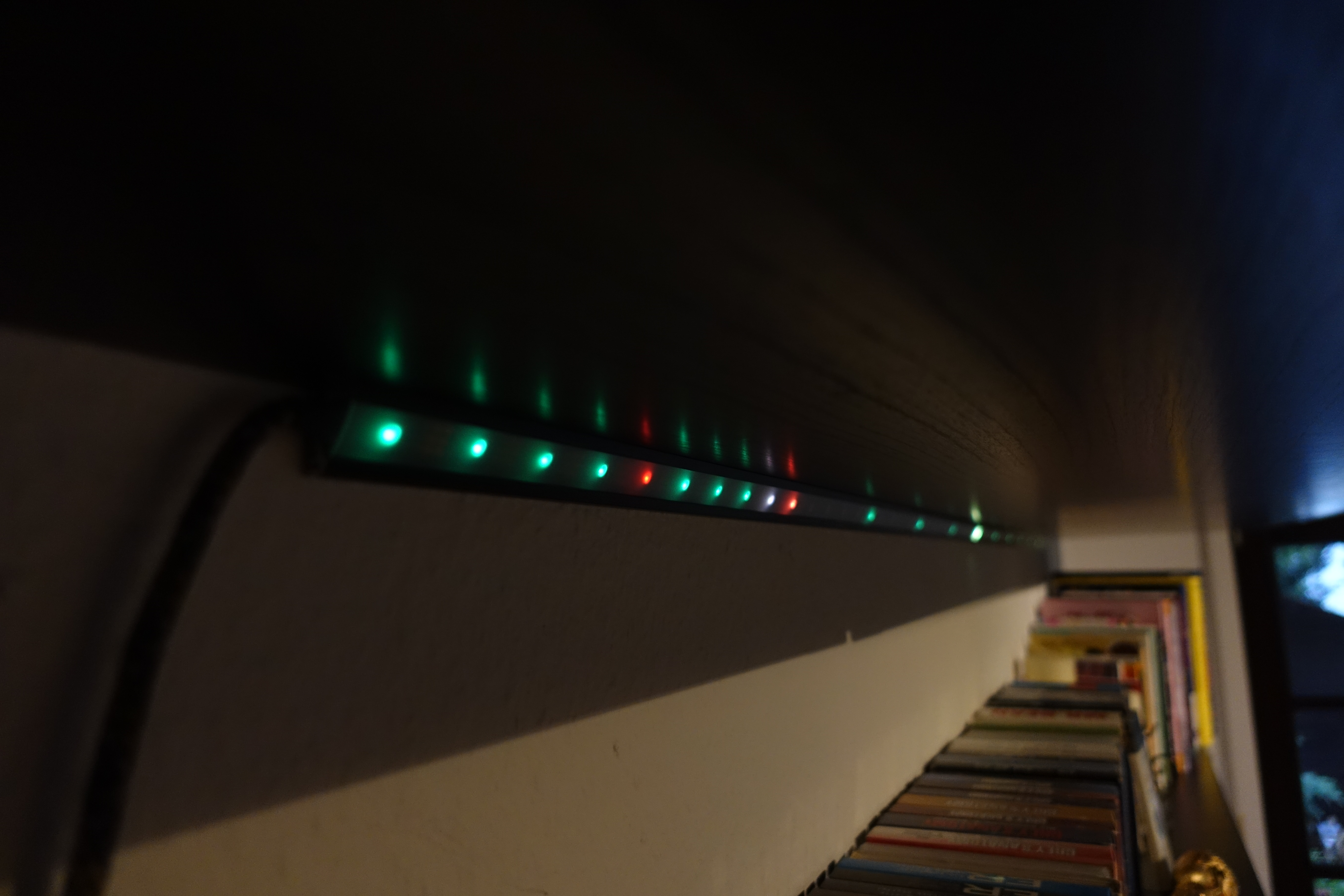
Compared to normal clocks, which have most commonly a circular shape, my StripClock is just a 2 metre linear strip consisting of 60 LEDs. You read it by counting the illuminated LEDs from left to right. Every lit LED corresponds to a minute gone past of the current hour. Additionally, every fifth LED is permanently lit up in a different colour. They serve two different purposes. For one as you might expect if you look at a normal clock, they correspond to the hours of the day (or half-day, as there are twelve). One of them is lit up in a third colour indicating the current hour.
Additionally, they can be used to more easily count the number of minutes gone by. Having to count for example 27 LEDs at the 27 minute mark would be quite tedious and very slow. Instead just have to count the hour markers left of the last lit up minute-LED (in this example five) plus the number of lit minute-LEDs after that hour marker (which would be two). So the minutes gone by are 5*5 + 2 = 27.
This sounds much more complicated than it actually is. And you get used to it very fast. What helps as well, if you have something indicating half of the strip, or the 30 minute mark as well. In our living room, the 30 minute mark sits where two cupboards meet.
Electronics
Looking at the huge list of different chips Atmel sells, I settled for the ATtiny4313. It only has 4 kB of flash memory and 256 Bytes of RAM and 18 pins, but still two interrupt pins, which was one of the requirements. For comparision, the ATmega328, commonly found in different Arduinos has 32 kB of flash and 2 kB of RAM. So quite a step down. Especially, on the RAM side.
As a real-time chip I used a Maxim DS1307, mostly because I knew them from past projects. Both chips are SMD parts. Why I didn’t opt for SMD resistors as well is a mystery to me now. Probably, because we just had plenty of through-hole resistors at home but not SMD ones. And we had to order the chips anyway.
The schematics itself is nothing fancy or special. I designed it in Eagle, but have changed to using KiCad in the meantime and am currently migrating them from Eagle to KiCad. The Eagle files of the current board can be found here. Though done really crappy I realise now…
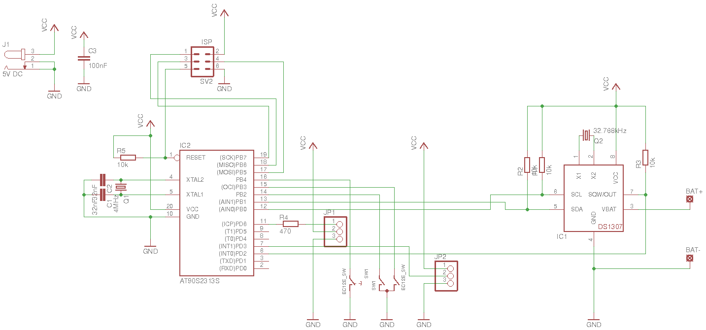
StripClock schematics
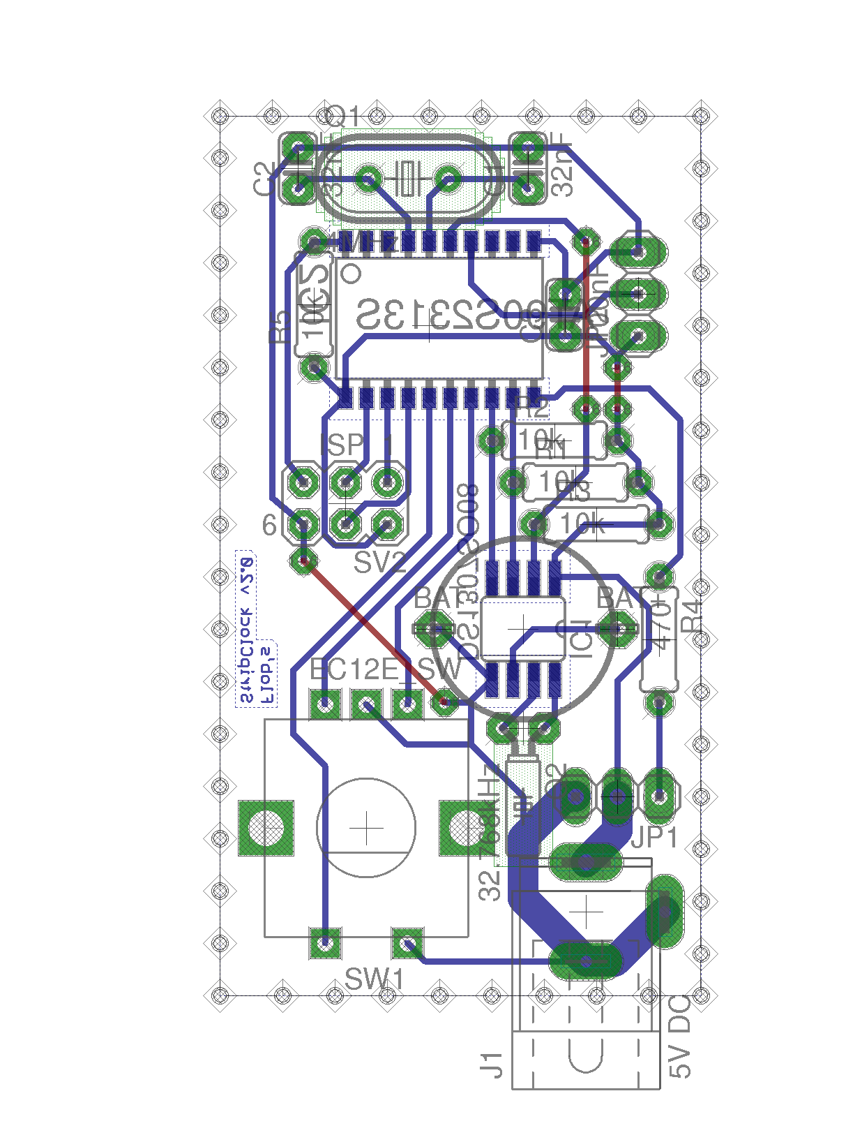
StripClock PCB
Since I wanted to etch the board myself, I was restricted to a single layer PCB and tried to keep the number of vias and bridges to a minimum. Routing might have been easier and nicer with an additional layer, but you have to work with what you got.
The rotary encoder is mainly used to set the time, but can or could also be used to set the brightness of the clock and switch it off and on.
JP2 is meant for an external DCF77 receiver, that I have never come around to attach and implement in software. Some day maybe…
The small coin battery is used as a backup-battery for the DS1307. In case of a power cut, the RTC won’t use the time this way.
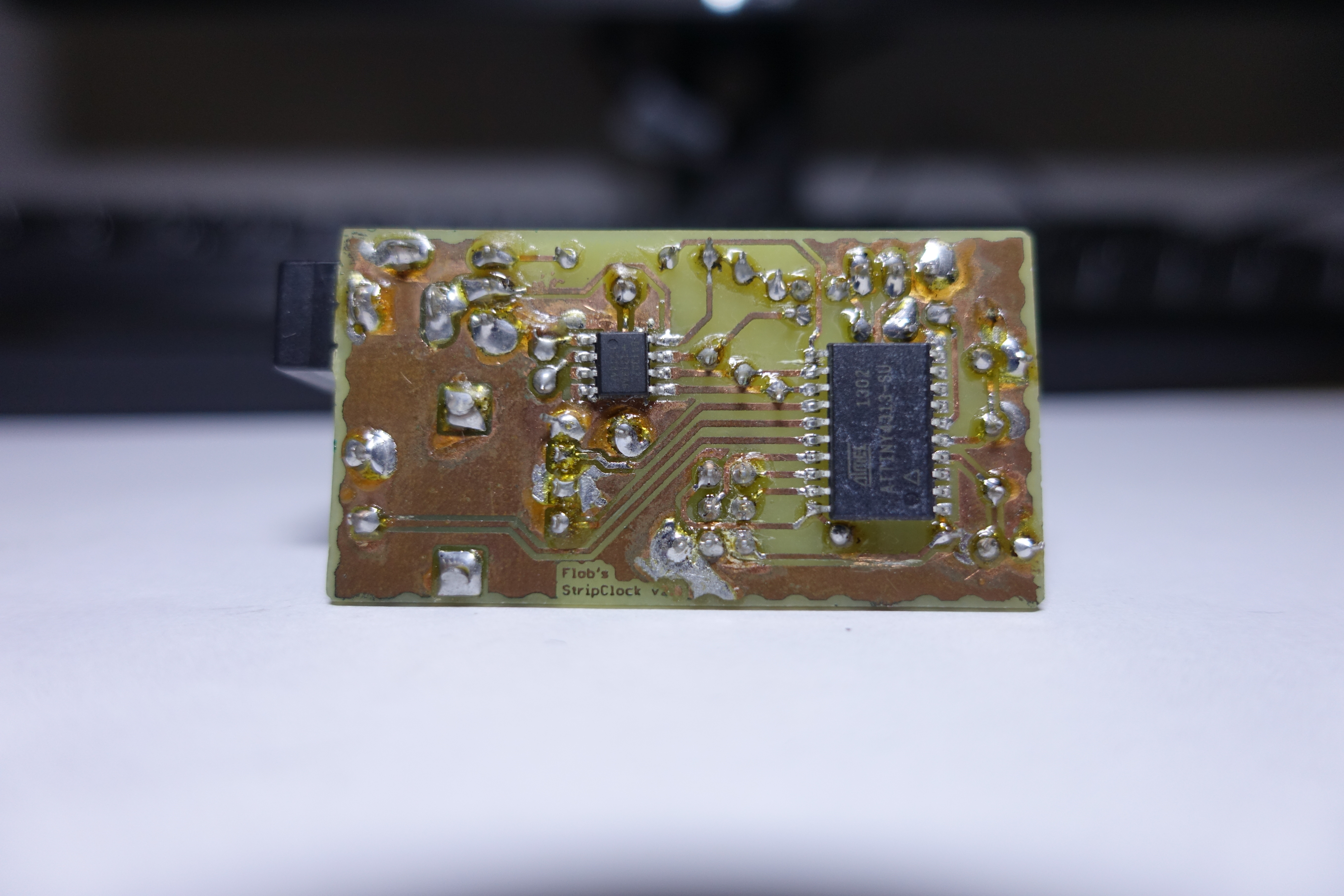
Back side of Clock module
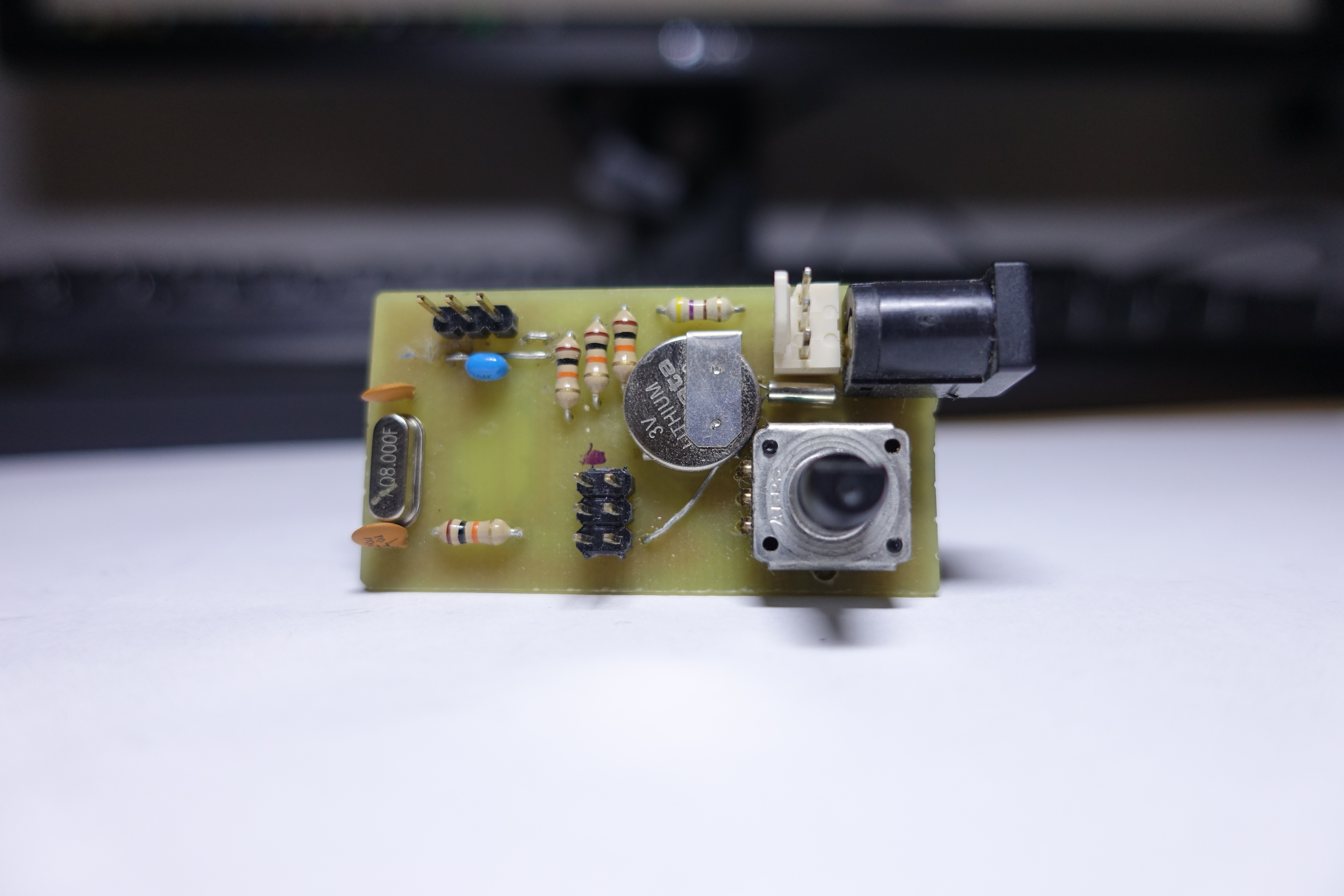
Front side of Clock module
Software
The code for the ATtiny4313 can be found here. I have to admit it is quite a mess. Especially if you look at the history. I have never been really good at tracking my projects in git. So commits are more often than not not very specific.
It uses the i2cmaster by Peter Fleury, which can be found on his website, to do the talking to the DS1307, as well as the light_ws2812 v2.0 by cpldcpu, which can be found on github.
Originally, I wanted to implement some colour effects, like fading in the currently running minute and such. But as it turns out fading colours is not that easy! Especially if you are resource-restricted and only work with the integer values you have to provide to the WS2812.
I later had a look at using a proper colour space representation like HSL and also implemented that. Unfortunately, to make that easy, you’d have to use floats. And since we are on a small microcontroller here, it doesn’t support float operations natively, but you’d have to implement them in software, which AVR GCC does. But the whole think doesn’t fit in the ATtiny4313’s flash and/or RAM… So I am kind of stuck with what I can do.
However there are plans, to upgrade the microcontroller in the future, to do proper colour effects.
So one thing I definitely learnt from it, is that yes you can down grade and save money, by going from a full Arduino to your own board, but don’t be too niggard if it is only a one-off thing, you are not done developing it as new features might require more power. So saving a buck or two by going from an ATmega328 to an ATtiny4313 is not worth it.
See that everything works, before you downsize.
-

- It is 11:02 (and some amount of seconds)

-
- Front side of Clock module
-
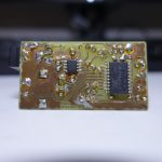
- Back side of Clock module
-
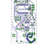
- PCB
-
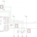
- Schematic
PS: We’ve never been bloggers much. I’d love to get some feedback, concerning where more detail would be good and style over all. 😉
Nice one 🙂
It’s a bit similar to mine: http://bogdan.nimblex.net/diy/2016/10/29/iot-fuzzy-clock.html but I definitely like the one you built better even though initially I just wanted to make a splash of color that ment something.