In an effort to counter my own forgetfulness to water the plant in my apartment and on my balcony, I tried myself on developing a soil moisture sensor device.
Since I wanted it to run on my balcony, where I don’t have the means to connect everything up to a power socket, it needs to be battery-powered device. And because it is supposed to integrate with my Home Assistant it needs wireless connectivity as well and not just a simple indicator light for example.
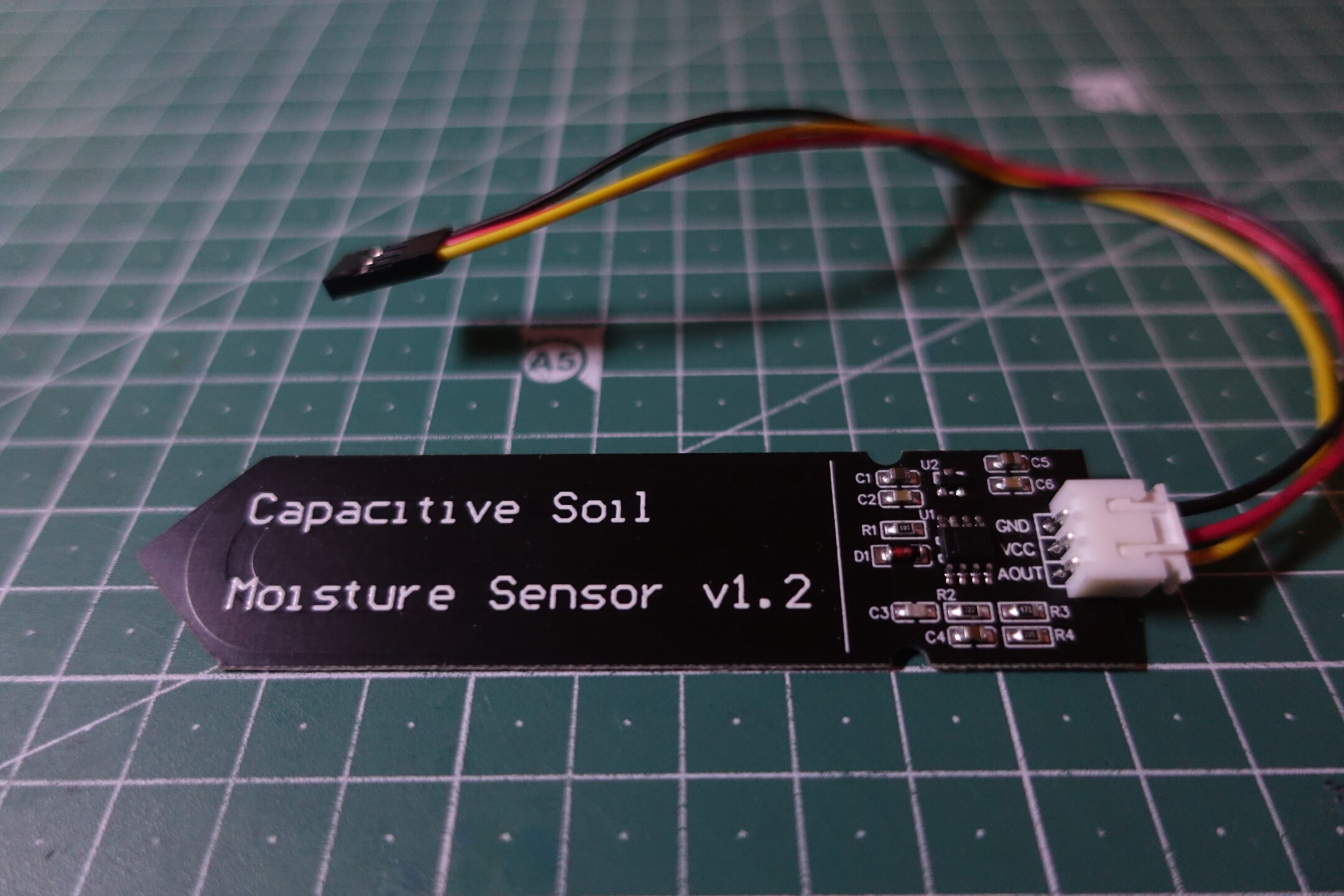
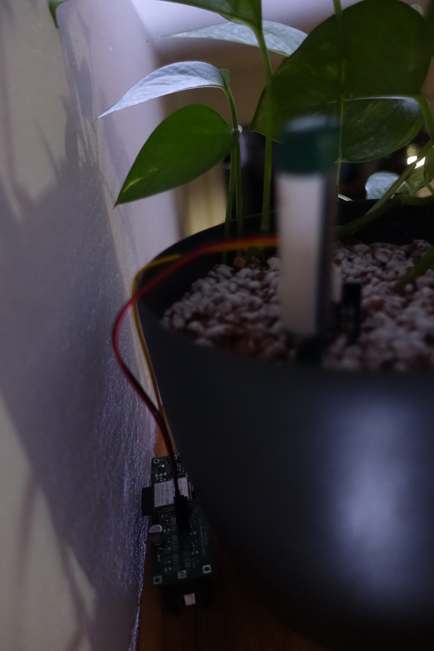
As sensors I came across these Capacitive Soil Moisture sensors, which are sold rather cheap, when sourced directly from China. They output an analog signal, which changes based on the capacitance of the surrounding material. The water contents of the soil gives enough of a change in it capacitance to change the senor’s reading.
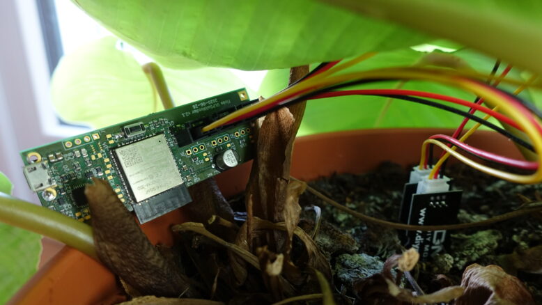
Being battery-powered, continuous monitoring of an analog signal and the ESP32 might not be the first thing that spring to mind, but I think I fitted them well together nonetheless. For one of my plants, the ULPSM has been running for over 6 months now on a single battery charge.
Power-saving measures
Using LiFePO4 batteries & dropping the LDO
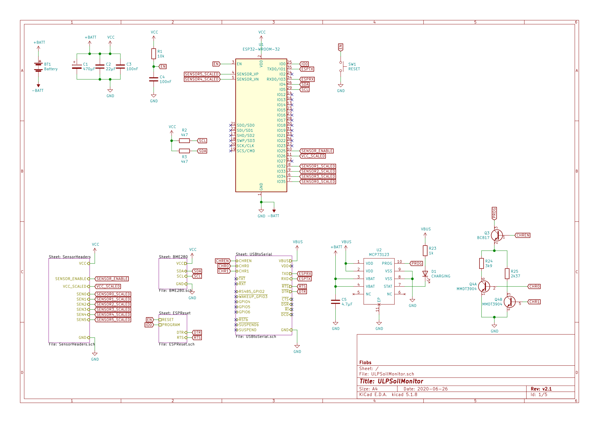
While LiFePO4 batteries have some disadvantages like lower power-density compared to Li-Ion batteries you normally see when battery powering an ESP32, they have the big advantage, that their voltage characteristics fit the required/allowed input voltage of the ESP32 much better, allowing to drop a voltage regulator.
Normally, you’d have a LDO for example, dropping the voltage of an fully charged Li-Ion battery from 4.2V, which is above the absolute maximum rating of the ESP32 down to 3.3V. However, the voltage of a fully charged LiFePO4 battery is “only” 3.6V, with a nominal voltage of 3.2V. It also has a rather flat discharge curve, around 3.3V to 3.1V, making at a great fit for the ESP32.

wdwd, Public domain, via Wikimedia Commons
While there are LDOs with very low quiescent currents, it can be still a major contributor to power consumption and getting rid of it will help out a lot in the long run.
I opted for a 18650 cell on each ULPSM, which have a capacity of about 1100mAh.
The moisture sensors have an additional LDO each as well, regulating the input voltage to 3V as well. I de-soldered them and am directly powering them from the battery as well. The input voltage for the sensors doesn’t matter too much, as long as it is relatively stable between measurements.
ESP32’s ULP co-processor
Letting the power-hungry ESP32 run all the time is of course not possible running on the battery. It would be empty withing a several hours.
Knowing that, the ESP32 provides several power saving modes, where in one of the deepest sleep states, the power consumption is down to a couple of μA.
One way would be to periodically wake the ESP32 from its deep-sleep, run the measurements, send the data and go back to sleep again. Certainly a feasible way, but depending on the wake frequency, you could trigger way to often, since the moisture content might change very slowly.
So can we do better? Yes, we can. The ESP32 does feature a Ultra-Low Power co-processor (ULP), next to the main Xtensa dual-core processor. Compared to the main processor, it is very much reduced in its features and it has to be programed directly using its small instruction set and only four registers. But isn’t that half the fun working in such a constraint environment? 🙂
Most importantly however, there is an instruction to use the two ADCs in the ESP32, allowing to read their values even with the main processor turned off.
I programmed the ULP to measure all sensors periodically and only wake the main processor, if at least one sensor changed its value more than some threshold value, compared to the last value transmitted.
Using this method and a sensible threshold, I get the optimum wake-up frequency. Either sleeping for hours or days at end, when there is no change or waking more frequently as the soil dries more quickly.
At the time, that I started the project, I think there was only (unofficial) support for programming the ULP using the Arduino IDE, using duff2013’s ulptool set. PlatformIO has support for adding ULP programs to your firmware binary now as well, though in a quick test, I think I couldn’t make it work back then.
Connecting the Sensors
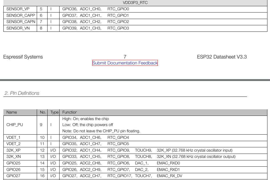
One of the down-sides of the ULP is, that not all GPIOs are accessible from it. Looking on the datasheet only pins that are labeled RTC_GPIO_* can be used. But as I mentioned, this includes several pins of the built-in ADCs.
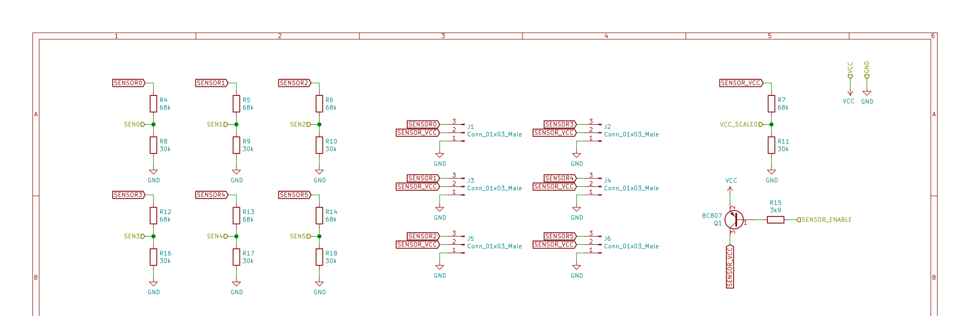
Being constrained by that, I was still able to use six channels as sensor inputs on ADC1, as well as an additional channel on ADC2 to measure the current battery voltage. This can both be used to compensate the sensor values, which are dependent on the input value, as well as monitor the battery voltage and warn when it runs out.
The ADC in the ESP32 normally only allows to measure voltages between 0V and about 1.1V. The measured voltage can be attenuated internally to provide a wider voltage range, at the expanse of a larger non-linearity and more noise. Instead I opted for simple voltage dividers on each of the sensors’ output, to regulate them to 1.1V at the maximum battery voltage of 3.6V.
Integration & Additional Periphery
As mentioned the ULPSM was supposed to integrate into my Home Assistant. And so it does using MQTT. Each device and sensor provide a topic the current moisture percentage is published to. Auto-discovery for Home-Assistant is implemented as well, meaning no additional configuration in required, but HASS will pick-up any new device on first boot.
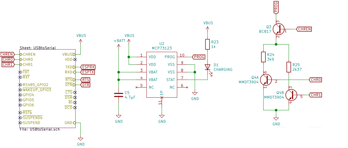
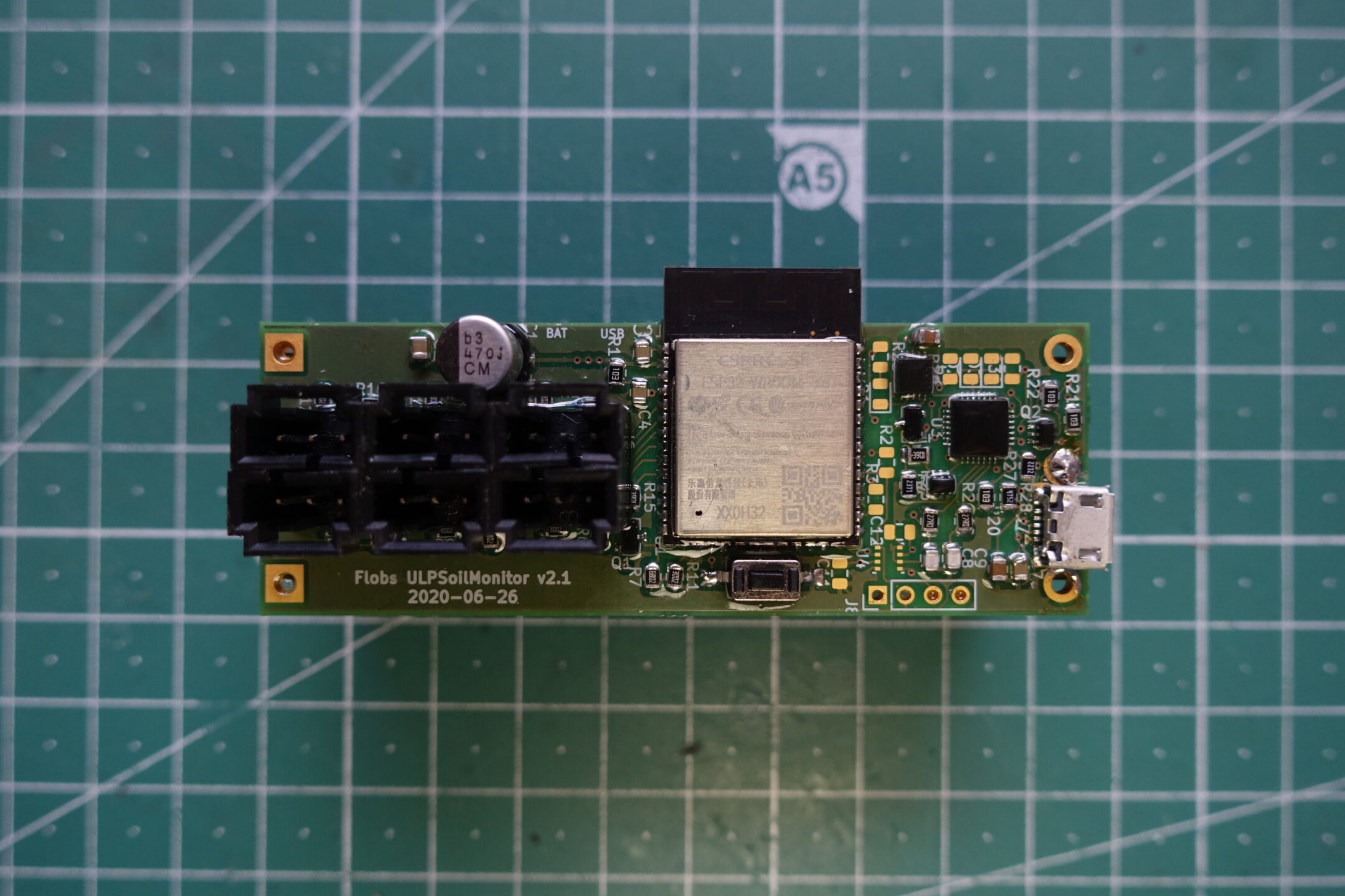
The ULPSM has a built-in CP2102N as a Serial-to-USB interface, together with a reset circuit, it allows to program the ESP32 directly from the Arduino IDE or PlatformIO.
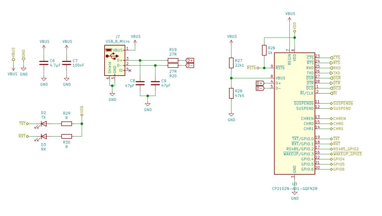
To charge the battery, there is also an MCP73123, a LiFePO4 Charger-IC, which can interface with the CP2102N to limit the maximum current it draws from USB, depending on what the port offers.
I haven’t used it that much yet, since I just change batteries instead. Also because I didn’t have to change them much, due to the overall low power consumption. 😉
There is also an unpopulated footprint for a BME280, in case you want to measure humidity & temperature of the surrounding area.
Results & Problems
As I mentioned earlier, I was able to have the ULPSM run on a single battery charge for about half a year now, while continuously monitoring a plant.
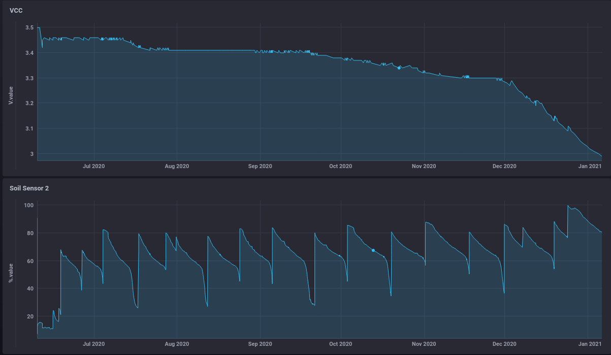
This is more or less a best case scenario, as there is only a single sensor connected to the ULPSM and the plant doesn’t consume water too quickly.
But even on the devices, where I do have all six sensors connected, which are in plant pots on my balcony, with sun shining on the in the summer, I got a couple of months of life time out of a single 18650 cell, which is good for me.
There are still a few problems to fix. But they are more related to the sensors, than the ULPSM hardware.
Water-proofness. The ULPSM, will read garbage values, in case the sensor connectors get wet. Who would have thought… I’ve seen a couple of people using shrink tube to protect the sensors. However, the sensor’s etch resist seems too peal off, after a while as well, probably changing the sensors characteristics over time. That’s what you get, if you go cheap from China. What I was thinking about, was coating both the sensors and the electronics with casting resin. But I haven’t gotten around to doing that yet.
Different Sensors. Depending on the seller you buy the sensors from or the batch you receive, the ADC values for low or high moisture can be completely different. In a newer version of the firmware I implemented a way to adjust each sensor. First the low or 0% moisture value is measured with the sensor in free air. Then measuring the 100% moisture value with the sensor dipped in water. Later the conversation from ADC value to moisture value is linearly interpolated between those values.
Even with adjusting the sensors, the measured values of two sensors next to each other in the same pot, often have an offset between each other. However their rate of change is very similar and the offset between them generally stays the same. I’ll have to look into that more systematically though.
The KiCad files and firmware source files can be found here and here.
Additional Resources
- ULPTool for Arduino IDE
- Video by Andreas Spiess about the ULP
The blog says
“The moisture sensors have an additional LDO each”
but I do not see an LDO on the sensors PCB. Can you please elaborate?
Regards
It is the component marked U2 on the sensor. Since it is black on black it’s a bit hard to see in the picture.
Are you planning to make this commercialy available?
I would order at least 1 of this boards.
Also have you considered to add a luminous sensor?
Hello Pedro, I was thinking about adding a luminous sensor at some point, but the board was already getting crowded as is. Additionally, I already have another device measuring luminosity in my home, so I didn’t really have the need. But there are some other minor improvements for the board, I had in mind. So I might have a look if I could fit one on there.
As for making them commercially available, I haven’t really planned it yet, no. Mostly, because I’ve never done that, I don’t really know if there was a market for it. ;D
Hello,
This is exactly what I’ve been looking for, if you do make them commercially available or even a small batch, I’d most definitely be interested in buying 1 or 2.
Regards
Ian
As you are already featured on Hackaday you might as well sell a few of them on Tindie which might actually help in offsetting some costs (or buy you a few pints of well earned beer!)
https://hackaday.com/2021/01/14/esp32-soil-monitors-tap-into-ultra-low-power-mode/
Hello René, I will look into it in the next couple of days. 🙂
Pedro, I would definitely buy a couple of these preassembled if you have a board already designed. I have a need for exactly what you have here.
Great work !! I love this. Can you put amazon links of items you have used ? Possibly video as well. Measuring light, temperature, and soil moisture is essential for anyone gardening.
Hello Bryant, glad you like it. 🙂
The only thing that was off the shelf really are the sensor itself, I bought a bunch via AliExpress. If you search for ‘capacitive soil sensor’ you’ll find them. Otherwise the ESP32 based board I developed myself and had it manufactured through aisler.net. You find the KiCad-files with BoM and everything to make a copy for yourself at the end of the post.
Please put these up on Tindie so I can buy two!
Hello Tim, glad you enjoy the project. I’ll have to see about that, especially how much they’d cost to manufacture and for how much I’d have to sell them not to take a loss. But you are free to make them yourself. 😉
Very interesting project, not sure I agree about lifepo batteries though. You can get LDO’s with quiescent current of <5uA, for instance see ezSBC dev boards. Then you have a much cheaper, higher density battery and the power loss from LDO is almost non-existant. You can also get battery fuel guage chips very cheaply which do all of the measuring for you, that might be more difficult with lifopo.
Using esp-now instead of plain wifi would massively reduce power consumption, but this would imply having another powered esp32 nearby. You can wake from deep sleep and send a message in around 200ms, instead of seconds for wifi. In that case the battery life should be years not months.
Hello Will, I must have not found them at the time I guess, interesting, not sure why.
The runtime including connecting and dropping off the messages via MQTT isn’t actually as bad as you think. I don’t know them for this specific project atm, but a similiar one takes about 700ms from wake up to going back to sleep. 250ms of those are in the bootloader though, which could also be reduced a bit. There are occasional spikes by pretty much exactly one second, which I haven’t quite figured out yet, must have something to do with the wifi protocol I guess.
That’s the slight problem with wifi, when it’s fast it’s fast but when it isn’t it can take a few seconds to connect which is a lot when it’s using hundreds of mA.
It may make sense to use http instead of mqtt, it should be quicker. MQTT is only supposed to be used for permanent connections.
Hi!
Thanks for creating this! I’ve been working on building a few of my own, but I can’t find any information on the 18650 cell holder. All I have is this footprint name: flobs-KiCad-footprints:BatteryHolder_BHC-18650-1P-2P. Do you have any information where you got yours?
I’ve made a few changes, mostly related to removing the USB-serial converter and replacing it with a programming header. All my work is at:
https://github.com/zrgravity/ULPSoilMonitor-KiCad
Current chip shortages mean the MCP73123 and (optional) BME280 are not available until August, so I may have to create a temporary power supply for testing a few of these.
Once again, thanks for creating this!
Hello, glad you like the project. The footprint you are missing is part of a library of custom footprint I made myself. Unfortunatelly, I don’t have it in version control yet. I’ll have to see about doing that. In the meantime here it is.
Yeah, the current chip shortage is a bit annoying. I still had a couple of MCP73123 left when I did the project. But there is nothing to special about it and could be easily replaced with another LiFePO charger I guess.
“However, the sensor’s etch resist seems too peal off, after a while as well, probably changing the sensors characteristics over time. ”
Sensors get water from the borders where the PCB was cut, that are not waterprooof. They must be waterproofed.
Great project. I’ve had this marked to read in my RSS feed reader forever, finally getting a chance to actually read over the details.
Some tips I picked up from other “low energy” projects, especially around the wifi client, set a static IP address. The wait on the DHCP client means wasting cycles just to get a response (learnt that here https://www.youtube.com/watch?v=2kLZ7DlP9KU).
On that same video, there is a tip on sending battery life notifications. Might be handy to drop a notification when voltage drops past a certain point, though
Remove serial output unless you need it for debugging. Use #IfDef to only compile in the debugging code as you need it. For example:
#IfDef DEBUG
serial.printf(“blahblahblah”);
#EndIf
Then have a central file that you define DEBUG in. This will reduce code size when not needed, and not start the serial code, and should help consume less power too.
Hello Jon, thank you for your comment and sorry for the laaaaaate reply.
Yes, DHCP (and WiFi in general) isn’t the most suitable mechanism for low powered devices. But at least the DHCP client does remember its last lease and can normally get around the whole DISCOVER cycle and re-establish an IP quite quickly.
I think there at least some concurrency, between WiFi/DHCP/MQTT connection establishment and the read-out of the sensors. So not all cycles are wasted. I do have a plan to re-implement the project using Espressif’s esp-idf directly, and making sure that does happen concurrently.
Also with using the esp-idf, it is easier to set a debug level to the serial output during compile time, which is also a reason, why I prefer it by now over Arduino.
The cheap chinese soilsensors have no coating! They will be defected after some month!
Thake the genuie one!
https://www.ramser-elektro.at/shop/bausaetze-und-platinen/giesomat-kapazitiver-bodenfeuchtesensor-erdfeuchtesensor-mit-beschichtung/
Yes, that is true. I have gotten some conformal coating for them though in the mean time, which does help with their longevity, similar to those from Giesomat.